 Tweet
Tweet
Love all the updates.
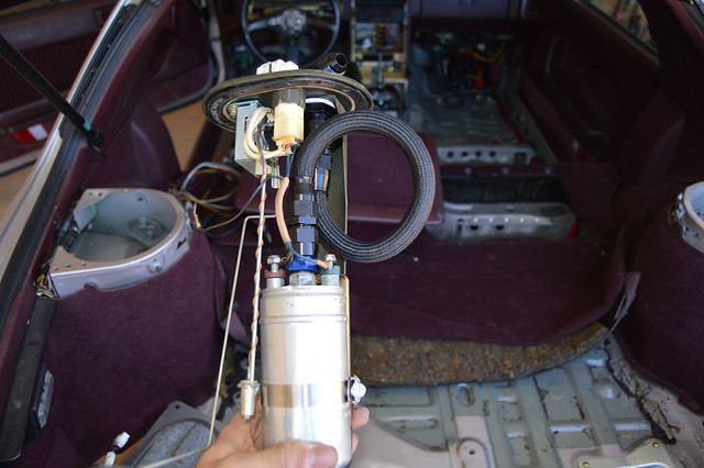
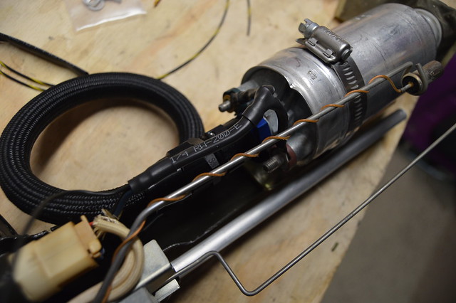
As far as the in tank fuel line. Call up some local race shops (or fab shops) to see if they have the tool to make a hard line and bring them your pump assembly to build the line (or rent the tool from them.)
As far as the in tank fuel line. Call up some local race shops (or fab shops) to see if they have the tool to make a hard line and bring them your pump assembly to build the line (or rent the tool from them.)

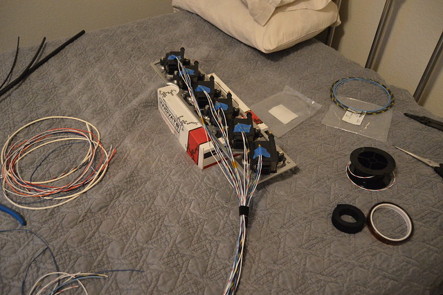


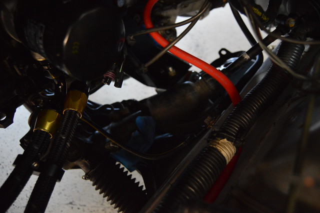
 That's what I'm affraid of with my project. I haven't hot wired my car before finishing the looms. So if something is interfering, I might just have a lot of un-wiring to do...


Comment