 Tweet
Tweet
So looks like photobucket is now supporting third party stuff again? Must have realized what a shitstorm they created. regardless i wont be supporting them anymore and sticking with flickr which is 10X easier to use.
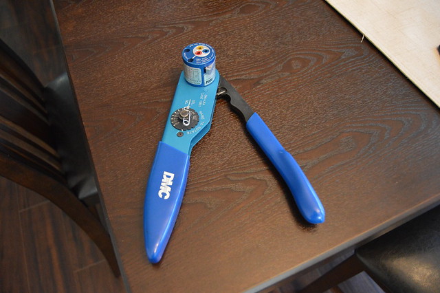
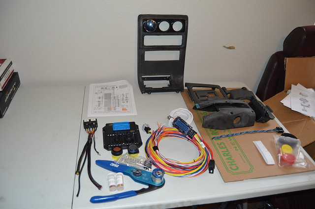
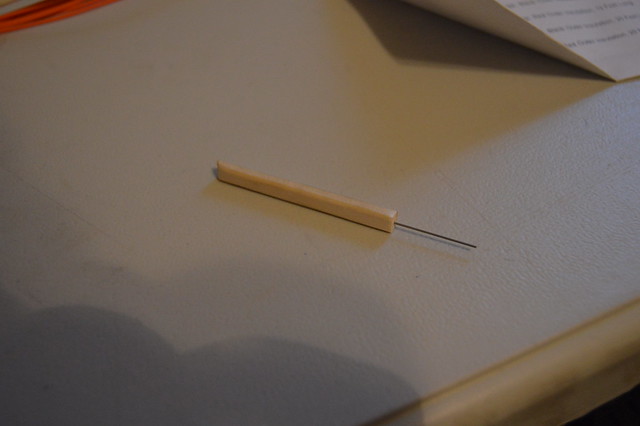
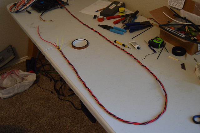
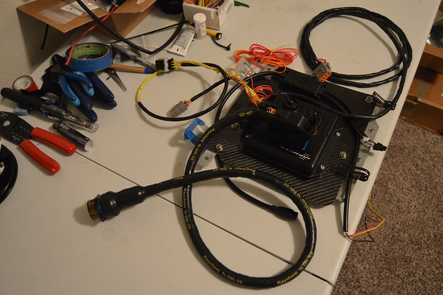
Found a smoking deal on this DMC crimp tool setup on ebay.

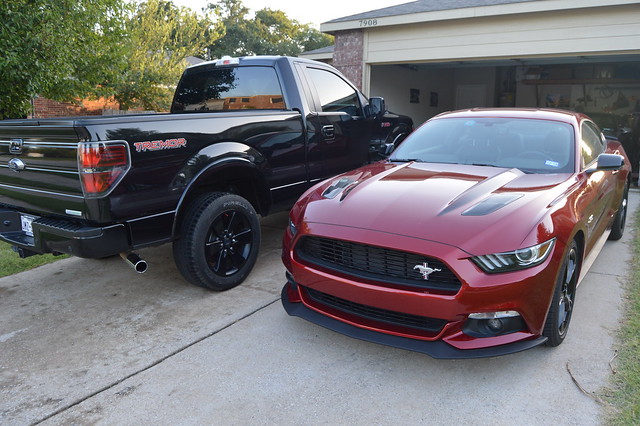
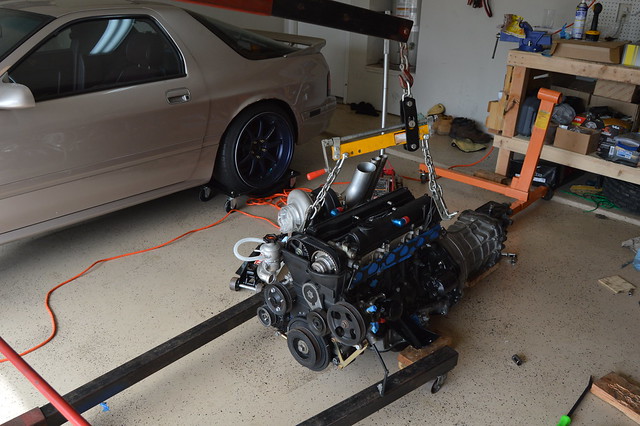
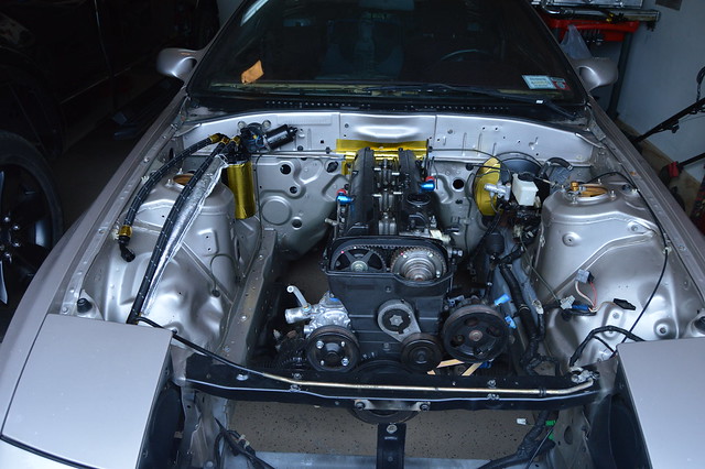
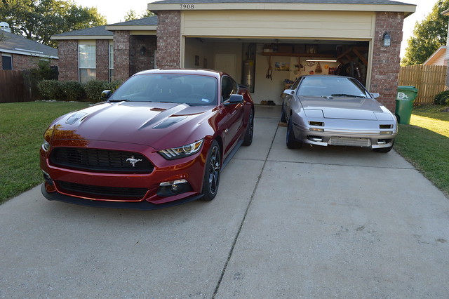
Washed up the rest of the fleet
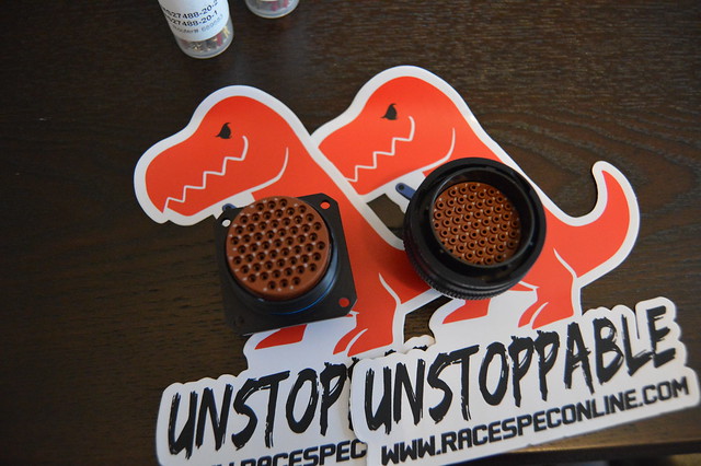
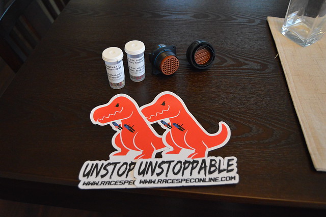
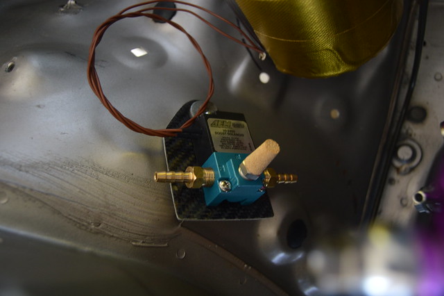
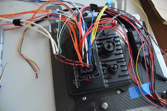
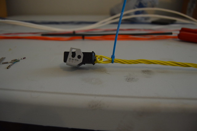
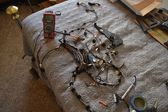
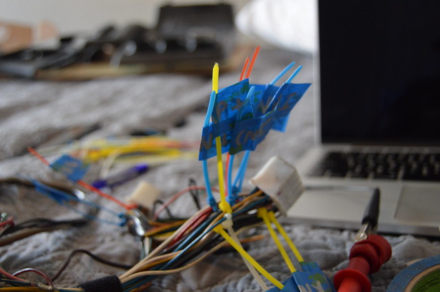
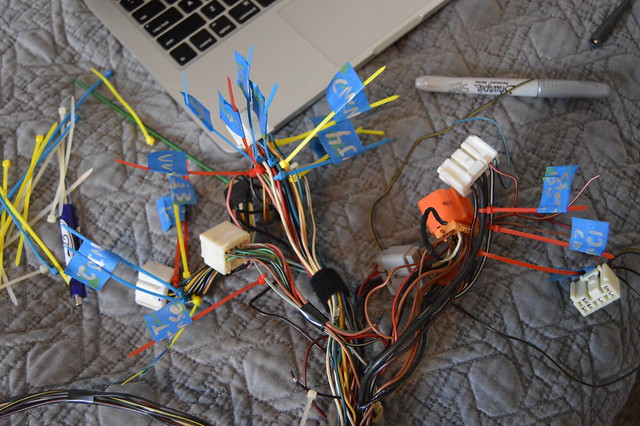
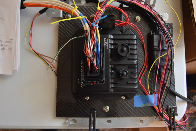
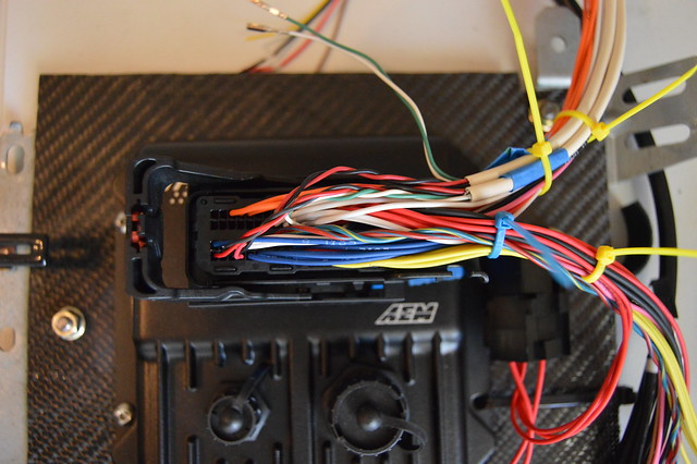
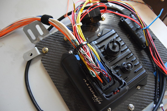
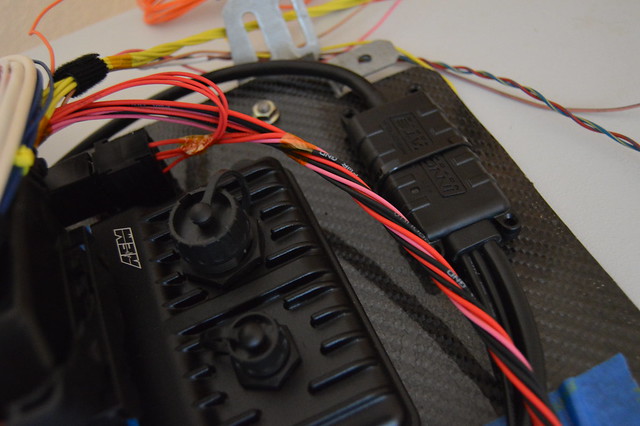
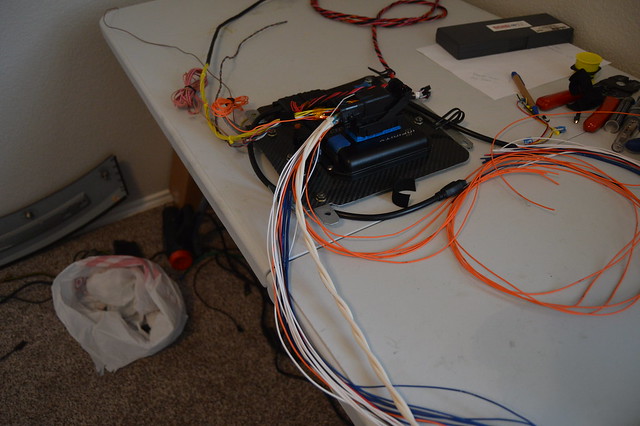
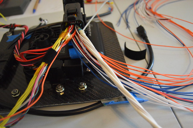
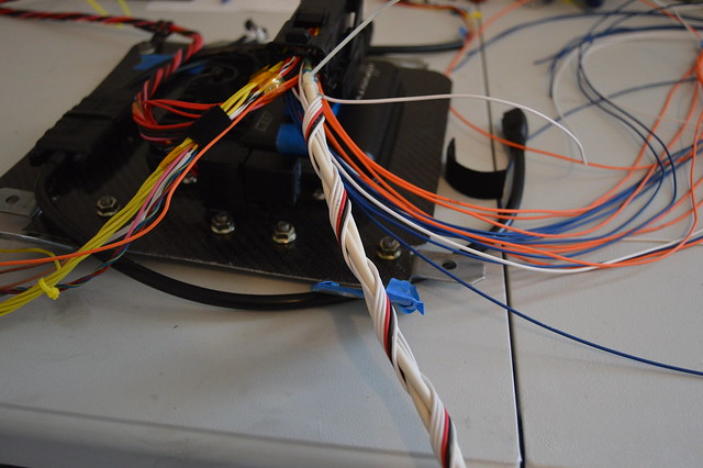
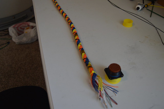
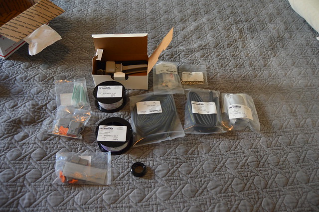
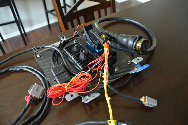
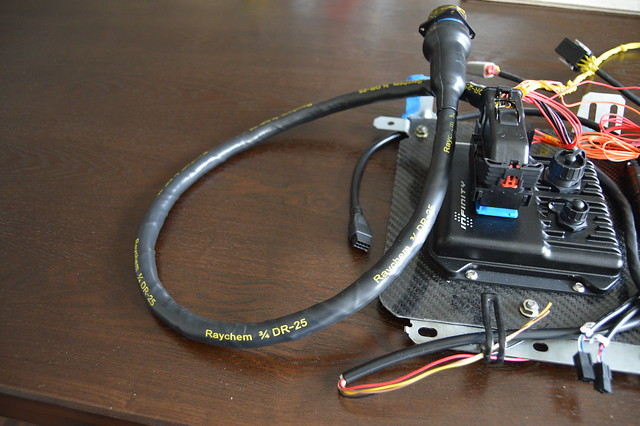
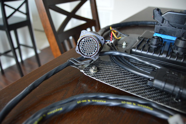
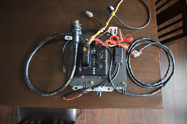
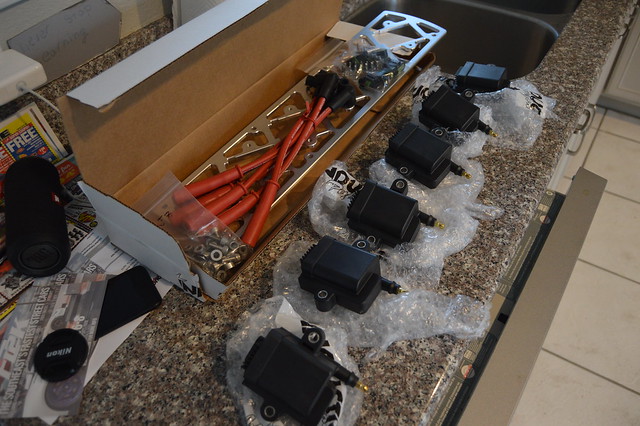
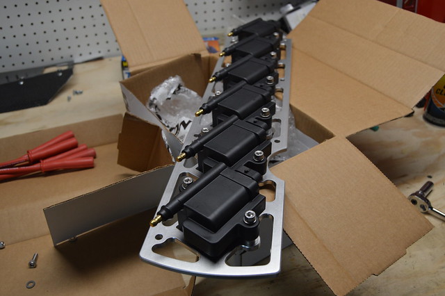
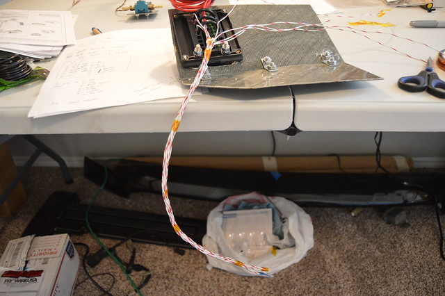
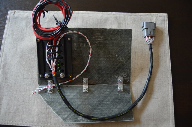
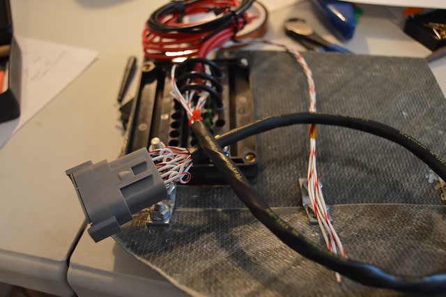
And got my connector kit in. Now i need to order up a fuel pressure, oil pressure, and ethanol content sensor then finish up planning out the harness and get to work.
Found a smoking deal on this DMC crimp tool setup on ebay.
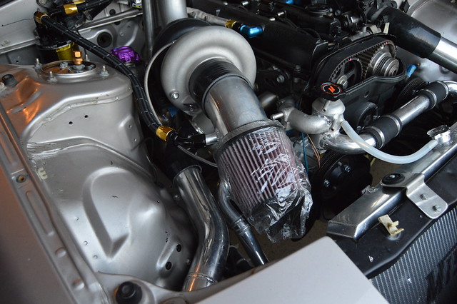
Washed up the rest of the fleet
And got my connector kit in. Now i need to order up a fuel pressure, oil pressure, and ethanol content sensor then finish up planning out the harness and get to work.


Comment