 Tweet
Tweet

-
-
So jazzed to see this dream build finally come to fruition!!!Stay wide my friends. @samthedandyComment
-
This quote is the realest shit I've ever read. Gave me the chills because I know the exact feeling you are talking about. For me, it happens with music and those perfect moments in life.Originally posted by Miroteknik View Post
You have an amazing story that is very well written and I really appreciate you taking the time to share with us here. Congrats on finally getting the chance to take the fc out. It looks great as is! Keep up the progress!Comment
-
Alternators all work the same... use rotor current to control charge output. (By induction to stator)if you use a factory harness The pcm should be controlling the regulator. Check and make sure your engine to batt batt chassis ground is okay. I could also see system seeing big
Voltage drop from
Batt to alternator (since batt relocate) module (pcm)may be monitoring output and seeing 14.2@output and 13.2 at batt..Last edited by Funtington; 05-02-2018, 11:27 PM."on our way back i hit a bump and both of the springs slip off of their seats and slashed both of my front tires."
-Dane M
If your not doing this, your doing it wrong.Comment
-
Originally posted by DaguerrotypeI View PostOriginally posted by 06RawRsx View Post
You have good information here. especially the bit about relocating the battery. The new + cable is about 12ft long, and the - cable is 2ft long, and grounded to the rear sheetmetal via a 10mm bolt. The ground from battery to chassis might not be adequate?Originally posted by Funtington View Post
I may try to run the negative to a better location, although there isn't much but sheetmetal back there.
THAT BEING SAID... I got tired of charging the battery and driving around wondering when the battery would run out of juice. I knew my alternator needed 5v to engage, and I knew that wasn't happening for some reason. Because I wasn't really sure where to start, I decided to find 5v elsewhere...
The ECM has 2 gray wires for diagnostics or something, that run 5v. I spliced into one of those, then into the alternator's EXCITER wire, and....
The alternator was charging at 14v!
Now that means its ALWAYS charging, and I don't know if that will kill my battery, or overload anything but..... it means I can drive the car now with the lights on, and not worry about getting stranded. I think.
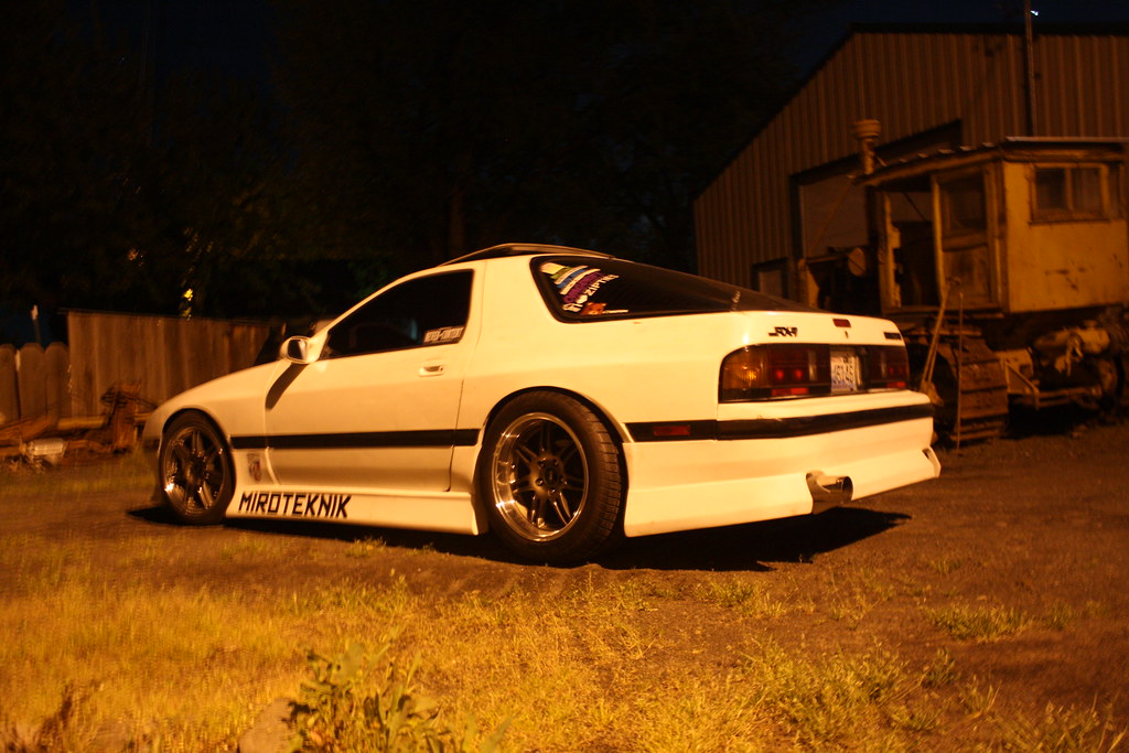
Took some pics this weekend but still haven't taken them off the camera, will get to that later. In the meantime, here's a pic after a midnight run.
xxxxLast edited by Miroteknik; 04-17-2019, 11:36 AM.
Comment
-
Do you have a pin out for the ECU that you are using? If so, let me see it.
And not all alternators are the same. Some vehicles use them as an alternator, others as a generator style application. Run a voltage gauge for now so you don't explode that battery due to over charge.Instagram: @Eurow
Comment
-
From my research: Looks like you need a 12v signal with a 470ohm 1/2 watt resistor inline that comes on with ignition power, or swap your alternator for a one wire unit.
on a F-body alternator pin B on the 4 wire plug should have a 12v source with a 470ohm 1/2 watt resistor inline in order to "turn on" the alternator. Well I tried that and it didnt work. Got a new alternator same thing. So last night in frustration I decided to leave the wire and resistor where it was and put 12v to pin C and BINGO! Alternator started charging and the gauge went to 14 volts.
So in my expirience, pin B needs the 12v w/470ohm resistor and pin c needs 12v in order for the alternator to energize.
This was a carb'd setup using a '98 camaro alternator (even though autozone only had one part number for 98-02 f-bodies)One differences is that the 98' alternator uses the light/resistor to reduce the voltage down.. the 99+ alternator uses the PCM feed with is already reduced to the correct voltage for pin B on the alternator to energizer..According to the wiring diagram, the alt should have 2 wires. The first big wire coming from the battery and the 2nd small red wire which comes from the charge light in the instrument cluster. The instrument cluster gets power from 2 different fuses, ip fuse 8 orange wire to cluster and fuse 9 pink wire to instrument cluster. Fuse 9 sends 12 volts to red wire of alt fuse 8 feeds a comparison voltage to cluster. No connection to computer, from factory.You can't use straight +12v on the wire. It needs a ~470 ohm resistor inline.Last edited by MikeyRa; 05-03-2018, 01:33 PM.Instagram: @EurowComment
-
Originally posted by MikeyRa View Post
is that off LS1-Tech? great site, used it to get the alt working the way it is now lol
unfortunately, most of the quotes you listed above do not apply, cause my engine and alternator are out of a 1994. my alternator has 1 wire (in the 4-wire plug), where the 98-02's, have 2 (in the 4-wire plug).
this quote:
"According to the wiring diagram, the alt should have 2 wires. The first big wire coming from the battery and the 2nd small red wire which comes from the charge light in the instrument cluster. The instrument cluster gets power from 2 different fuses, ip fuse 8 orange wire to cluster and fuse 9 pink wire to instrument cluster. Fuse 9 sends 12 volts to red wire of alt fuse 8 feeds a comparison voltage to cluster. No connection to computer, from factory."
confuses me, because my SMALL RED WIRE is called an exciter wire, and it comes from the ECM, it does not come from the charge light in the instrument cluster. which makes the rest of the quote even more confusing.Last edited by Miroteknik; 09-07-2018, 02:42 PM.Comment
-
So basically, the alternator you have is a two wire. One wire to battery and one wire to "excite" it. A one wire would only have one going to battery. The wire that signals the alternator to charge from factory goes from ecu, to the battery light in your dash to the alternator. Since you no longer have the factory dash setup, you would use the resistor to simulate the bulb on that wire. And just for good measure, the small excitor wire needs to be switch on ignition.Instagram: @EurowComment
-
Yes! That sounds like my setup. Lol I am just now starting to understand the whole path that the exciter wire runs. That also explains why I could not ring from the alternator-end of the exciter wire, to the red wires I found in the ECM plugs with a tester.Originally posted by MikeyRa View Post
Not sure when I will go back over it and wire it properly, but thanks for your input, I have a better idea of what may be going on.Comment
-
Anytime man! Automotive electrical is my time to shine, MECPs/ASEs on deck, lol, let me know if I can help in any way!Instagram: @EurowComment
-
Much appreciated my dude. I am embarrassingly incapable in electrical.Originally posted by MikeyRa View Post
So uh... I got the electric fan working lol. Hooked it up to my oem fog-light switch. Which means the headlights have to be on/up in order for the fog-light switch to work, and power the fan lol. If you see me rolling through the streets in the middle of the day popping up my headlights in broad daylight, you'll know why.
---------------------------------------------------------------------------------------------------------------------------
Also, I drove the car to work for the first time and had a moment.

XXXXLast edited by Miroteknik; 07-19-2018, 12:41 PM.Comment
-
Yea man, to explain it a bit more: The exciter wire goes through the dash bulb then to the alternator for a nice, simple reason, to let you know your shit isn't working. Basically, the 12v signal goes from ECU to bulb then to alt, and since the alternator is drawing and using the signal, the bulb doesn't illuminate. Now if for any reason the alt isn't charging, i.e. belt came off or alt is actually bad, the voltage on that exciter wire has no where to go except the bulb. And TADA your warning light is now on letting you know shit ain't good.
Also, if that bulb burns out or the filament breaks, the alt wont charge since the 12v signal can't pass thru a broken bulb. That's what the resistor simulates on your setup, a good inline bulb.Instagram: @EurowComment
-
For your fans, use one of these:

Instagram: @EurowComment
-
Love to see that your dreams come true.
I loved the ups and downs on the all build and your love for the build to go on and get it running.
I hope this build doesn't end here.
Comment

Comment